画像をダウンロード 115/230 volt motor wiring diagram 302895-115/230 volt electric motor wiring diagram
Overall Motor Length = 1269 inches, motor name plate shows wiring diagram ;Yes, those are not standard wire colors Use the numbers instead 1&2 are a 115 volt run winding 3&4 are the other 115 volt run winding 5&8 are a 115 volt start winding It'll be easy to figure out which wires are 1 and 4 The 230 volt connection will be one of the incoming hots to 1 2,3 and 5 spliced together The other incoming hot splicedCentury Ac Motor Wiring Diagram 115 230 Volts from wwwspapumpsandmorecom To properly read a cabling diagram, one offers to know how the particular components in the program operate For instance , when a module will be powered up also it sends out a new signal of fifty percent the voltage and the technician does not know this, he would think
Www Egr Msu Edu Bae Sites Default Files Content Docs Technote103 Pdf
115/230 volt electric motor wiring diagram
115/230 volt electric motor wiring diagram-WIRING DIAGRAM (For "EM I3D/R" Two Pole, Single Phase, 3600 RPM, 115/230 volt, ExplosionProof , and "EM4", Two Pole Single Phase, 3000 RPM, 115/230 volt, ExplosionProof motors, Manufactured by Reliance Electric) Direction of rotation is considered as viewed facing the fan cover of the motor All connections shown are forYes, those are not standard wire colors Use the numbers instead 1&2 are a 115 volt run winding 3&4 are the other 115 volt run winding 5&8 are a 115 volt start winding It'll be easy to figure out which wires are 1 and 4 The 230 volt connection will be one of the incoming hots to 1 2,3 and 5 spliced together The other incoming hot spliced


Diagram Century Ac Motor Wiring Diagram 115 230 Volts Full Version Hd Quality 230 Volts 6387 Vincentescrive Fr
Wiring Diagram Motor Ao Smith – All Wiring Diagram Data – Aosmith Motors Wiring Diagram Wiring Diagram not just gives comprehensive illustrations of everything you can perform, but additionally the methods you ought to follow although doing soHome Forums Hardware Design General Electronics Chat Need help wiring cord to a 15 hp 115/230 volt motor!Wire a 240 Volt Motor Electrical Question What do the L1 L2 and T1 T2 wiring diagram abbreviations mean when wiring an electrical motor?
2 volt electric motor wiring diagram, 240 volt electric motor wiring diagram, 230 volt electric motor wiring diagram, 115/230 volt electric motor wiring diagram Related posts 12 2 Volt Electric Motor Wiring Diagram 12 Electric Motor Wiring Diagram 2 12 Adams Rite Electric Strike 7400 Wiring Diagram 18 3 Wire Electrical WiringCentury ac motor wiring diagram 115 230 volts You should find the series and parallel connections on a diagram affixed to the inside of the terminal box cover 115 230 motor wiring diagram 2hp this is images about 115 230 motor wiring diagram 2hp posted by maria nieto in 115 category Re wiring a leeson volt motor to replace currentMy electrical wiring project involves wiring a 240volt motor I am trying to run power to a 240volt electrical motor I bought but I do not know what the abbreviations mean and how to read the diagram that came with the new motor
I'm wiring a new pump (USQ1072) for 115v operation The old pump's diagram (115v) has Line on L2 New pump's diagram suggests Line on L1 (Note the text "Neutral Line" confuses me) I understand that it really doesn't make a difference, as long as my Line (in) is the side that is switched (which is is), so the motor is not left "hot" when I115 230 Volt Wiring Diagram Schematic Wiring Diagram – Century Ac Motor Wiring Diagram 115 230 Volts Wiring Diagram comes with several easy to adhere to Wiring Diagram Guidelines It's supposed to help each of the common person in creating a suitable system These instructions will probably be easy to comprehend and applyCentury Ac Motor Wiring Diagram 115 230 Volts Source mainetreasurechestcom Before reading a new schematic, get acquainted and understand each of the symbols Read the particular schematic like a new roadmap


3


Need Wiring Diagram For Baldor 1hp Single Phase Motor
2 Sd Motor Wiring Need A Guru Pre 1950 Antique Fan Collectors Association Afca Forums Century 230 115 motor wiring diagram volt electrical 1990 marathon electric ac leeson reverse single phase motors baldor 1hp gravely vac schematic viking wire a gould waterway spa pump 2 sd hp 3450 rpm air need practical machinist largest techtop diagrams daisy electricity 101 basic fundamentals fan full 3 4The Advantages of a 240 Volt Motor Wiring a 1/240 volt motor for 240 volts is as follows A balanced electrical load which may save on electricity compared to an unbalanced electrical load Faster starting power 240 volt motors will have a stronger start compared to a 1 volt motorCentury Ac Motor Wiring Diagram 115 230 Volts from wwwspapumpsandmorecom To properly read a cabling diagram, one offers to know how the particular components in the program operate For instance , when a module will be powered up also it sends out a new signal of fifty percent the voltage and the technician does not know this, he would think
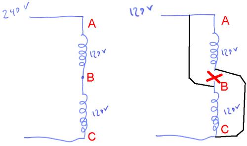


Switching A Motor Between 240 And 1 Volts


How To Wire A Pool Pump Inyopools Com
September 18, 18 by Larry A Wellborn Variety of century ac motor wiring diagram 115 230 volts A wiring diagram is a streamlined conventional photographic representation of an electric circuit It shows the parts of the circuit as simplified shapes, as well as the power as well as signal connections between the toolsWiring Data Diagram – Blower Motor Wiring Diagram Manual 00 npr izuzu blower motor wiring 13 ford e250 blower motor resistor and connector wiring international Blower Motor Resistor Diagram 12 24 Volt Trolling Motor Wiring DiagramCentury Ac Motor Wiring Diagram 115 230 Volts – century ac motor wiring diagram 115 230 volts, Every electric structure consists of various diverse parts Each component ought to be placed and linked to different parts in specific way If not, the structure won't function as it should be


Diagram Wiring Diagram Motor Ao Smith Full Version Hd Quality Ao Smith Pandiagram1f Portoniathos It


Diagram Suzuki 230 Wiring Diagram Full Version Hd Quality Wiring Diagram Ladderdiagram Tickit It
Single Phase Motor Wiring Diagram With Capacitor – baldor single phase motor wiring diagram with capacitor, single phase fan motor wiring diagram with capacitor, single phase motor connection diagram with capacitor, Every electrical arrangement is made up of various unique pieces Each component ought to be placed and linked to different parts in particular mannerCentury Ac Motor Wiring Diagram 115 230 Volts from wwwspapumpsandmorecom To properly read a cabling diagram, one offers to know how the particular components in the program operate For instance , when a module will be powered up also it sends out a new signal of fifty percent the voltage and the technician does not know this, he would thinkElectric Chain Hoist Wiring Diagrams 1 PHASE, 115/230 VOLT RECONNECTABLE, SINGLE SPEED HOIST (Electronic Limit Switch) January, 08 COPYRIGHT 08, Yale LiftTech, division of Columbus McKinnon Corporation PART NO


Http Vintagemachinery Org Pubs 1141 1405 Pdf


Practical Machinist Largest Manufacturing Technology Forum On The Web
Need help wiring cord to a 15 hp 115/230 volt motor!Item 10 3/4 HP / Volt AC RPM Motor Dayton K56AAA01, AC Motors Base on the wiring diagram displayed on the data plate of the motor I have an old Emerson 3/4 hp motor model KS60CX and would like to wire it up wiring, and it looks like there is an unused port where electric usually is internal wiring and diagram (see pics) Voltages labeled , If you cannot, a Century AC motor wiring diagram2 HP Electric Motor 56C Frame 5/8" Shaft Single Phase 115/230 Volt 3450 RPM TEFC Add to Cart Add to Cart Add to Cart Add to Cart Add to Cart Add to Cart Customer Rating 41 out of 5 stars easy to wire, might buy another in future Read more Helpful Report abuse Ralph C Walker 50 out of 5 stars Great motor Reviewed in the United


How To Wire A Baldor Motor 115 230 Cat No L1406t It Has Six Wires Wich Do I Conect


Century Motors Wiring Diagram 05 Mazda Tribute Wiring Harness Begeboy Wiring Diagram Source
Yes, those are not standard wire colors Use the numbers instead 1&2 are a 115 volt run winding 3&4 are the other 115 volt run winding 5&8 are a 115 volt start winding It'll be easy to figure out which wires are 1 and 4 The 230 volt connection will be one of the incoming hots to 1 2,3 and 5 spliced together The other incoming hot splicedCentury ac motor wiring diagram 115 230 volts You should find the series and parallel connections on a diagram affixed to the inside of the terminal box cover 115 230 motor wiring diagram 2hp this is images about 115 230 motor wiring diagram 2hp posted by maria nieto in 115 category Re wiring a leeson volt motor to replace currentIf the motor's rating is less than 15 Amperes FLA or RLA (you will find these figures on the label), you can run the motor on 1VAC provided that you have verified that the motor's internal wiring is set up for 1VAC The motor will have an enclosure for field connections A wiring diagram should appear there or on the motor's frame
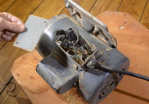


Switching A Motor Between 240 And 1 Volts


Magnetek Century Motor Wiring Diagram Mopar 440 Engine Diagram For Wiring Diagram Schematics
If it says 115/2 also, there should be a wiring diagram as part of the nameplate or under the cover where the cord goes in How is the old motor wired?I need the wiring diagram for a Magnetek century AC motor Serial # BS Its a 1/2 hp 115/230 volt, type CSR cat C337, part 8 single phase There are 9 wires, 8 are dead end in the box on the side of the motorThis is the point where you need to attach the ground wire As for the A plug and receptacle find a "NEMA 5R" and "NEMA 5P" from your local hardware store see image for visual reference Your wiring from the circuit breaker / fuse to the motor should be a minimum of 12AWG wire size to handle the current safely


Www Powertransmission Com Issues 0917 Baldor Basics Pdf


Single Phase Induction Motors
Special Mounting Motor pivots on rod for belt tensioning Totally enclosed fan cooled motor produces extra highW2 cj2 ui vi wi w2 cj2 ui vi wi a cow voltage y high voltage z t4 til t12 10 til t4 t5 ali l2 t12 tiblu t2wht t3org t4yel t5blk t6gry t7pnk t8red t9brk red tiocurry tiigrn t12vlt z t4 til t12 tio til Start capacitors run capacitors for electric motors WIRING DIAGRAM (ForTotally Enclosed Fan Cooled, Electrically Reversible;


Hallmark Industries Ma0505a Ac Motor 1 2 Hp 1725 Rpm 1ph 60 Hz 115 8 230v Ac 56c Tefc Cap Start With Foot Sf 1 15 Steel Pack Of 1 Amazon Com Industrial Scientific


230 Volt Schematic Wiring Chevy Camaro Wiring Diagram Contuor Nescafe Jeanjaures37 Fr
15 hp 3450 RPM, 0/100 amps, 115/230V, 60hz;115/230 Volt Motor Wiring Diagram Source detoxicrecenzecom Read electrical wiring diagrams from bad to positive plus redraw the signal as a straight collection All circuits usually are the same voltage, ground, single component, and changesBaldor Motor Wiring Diagram – baldor 5hp motor wiring diagram, baldor brake motor wiring diagram, baldor dc motor wiring diagram, Every electrical structure is composed of various diverse parts Each component should be set and connected with different parts in particular way If not, the arrangement will not function as it should be


Diagram Database Just The Best Diagram Database Website


Diagram Baldor Wiring Diagram 56c 115 230 Full Version Hd Quality 115 230 Diagramunlikelihood Nuitdeboutaix Fr
Always use wiring diagram supplied on motor nameplate w2 cj2 ui vi wi w2 cj2 ui vi wi a cow voltage y high voltage z t4 til t12 10 til t4 t5 ali l2 t12 tiblu t2wht t3org t4yel t5blk t6gry t7pnk t8red t9brk red tiocurry tiigrn t12vlt z t4 til t12 tio tilSingle Phase Motor Wiring Diagram With Capacitor – baldor single phase motor wiring diagram with capacitor, single phase fan motor wiring diagram with capacitor, single phase motor connection diagram with capacitor, Every electrical arrangement is made up of various unique pieces Each component ought to be placed and linked to different parts in particular mannerIn North America, many single phase motors motors in the range of 1 hp to 2 hp can be rewired to run at either 1 volts or 240 volts (or 115 vs 230 volts, it depends on what voltage is assumed "nominal") Such motors will typically have six leads coming out of the motor to the wiring box, or some of the connections may be screw terminals
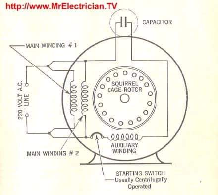


Single Phase Electric Motor Diagrams
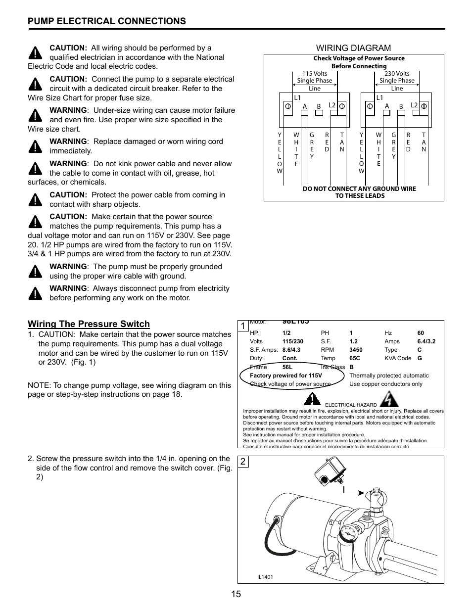


15 Pump Electrical Connections 1wiring The Pressure Switch Wiring Diagram Flint Walling Cpjs Shallow Well User Manual Page 15 24
Baldor Single Phase 230v Motor Wiring Diagram Collections Of Dayton Electric Motors Wiring Diagram Sample Baldor Electric Motor Wiring Diagram Elegant Ge Electric Motors Baldor Reliance Industrial Motor Wiring Diagram New Wirh Baldor 5 Hp Electric Motor Single Phase Wiring Diagram Beautiful SingleBudgit BEHC Wiring Diagrams Subject Columbus McKinnon Budgit Electric Hoist Wiring Diagrams, 1 Phase, 115/230 Volt Reconnectable, Single Speed Hoist Wiring Diagram Keywords Columbus McKinnon Budgit Electric Hoist Wiring Diagrams, 1 Phase, 115/230 Volt Reconnectable, Single Speed Hoist Wiring Diagram Created Date ZElectric Motor Wire Marking & Connections For specific Leeson Motor Connections go to their website and input the Leeson catalog # in the "review" box, you will find connection data, dimensions, name plate data, etc wwwleesoncom Single Phase Connections (Three Phasesee below) Single Voltage


How To Wire A Pool Pump Inyopools Com


3 Hp 1740 Rpm 115 230 Vac Leeson Motor P184c17dk3a New Arrivals Www Surpluscenter Com
What is the wiring diagram for a GE 115 volt electric motor, model# 5kc43mg48, 1/2 hp 1725 rpm 60 cycles want to wire to Answered by a verified Electrician We use cookies to give you the best possible experience on our website It has a GE motor w/9 leads, is a 1/3 hp, 115/230 volt, 1725 rpm, & frame 56In North America, many single phase motors motors in the range of 1 hp to 2 hp can be rewired to run at either 1 volts or 240 volts (or 115 vs 230 volts, it depends on what voltage is assumed "nominal") Such motors will typically have six leads coming out of the motor to the wiring box, or some of the connections may be screw terminalsWith the help of Frank from Franks Motor Shop it is shown how to easily, safely and quickly to wire a 3/4hp electric motor in this video These same instruct


Diagram 230 115 Volt Motor Wiring Diagram Full Version Hd Quality Wiring Diagram Wiringplus Aspetitjeancyclo Fr


Http Www Magnumlift Com Ams Aos Old Code Diagram Pdf
I have a Baldor motor model number CHC3417A Its a 1/3 hp 115/230 volt 1100 rpm motor I need to wire it to plug into a household outlet It has 3 internal wires (brown, white and yellow) and one exte read moreThis is the point where you need to attach the ground wire As for the A plug and receptacle find a "NEMA 5R" and "NEMA 5P" from your local hardware store see image for visual reference Your wiring from the circuit breaker / fuse to the motor should be a minimum of 12AWG wire size to handle the current safelyW2 cj2 ui vi wi w2 cj2 ui vi wi a cow voltage y high voltage z t4 til t12 10 til t4 t5 ali l2 t12 tiblu t2wht t3org t4yel t5blk t6gry t7pnk t8red t9brk red tiocurry tiigrn t12vlt z t4 til t12 tio til Start capacitors run capacitors for electric motors WIRING DIAGRAM (For
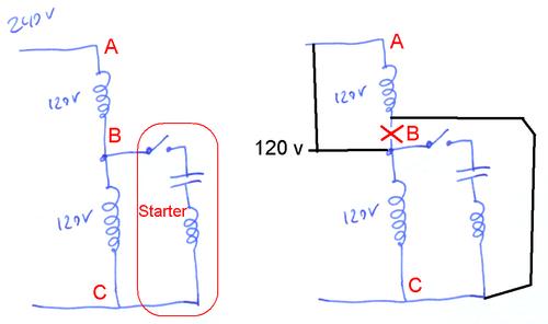


Switching A Motor Between 240 And 1 Volts


Practical Machinist Largest Manufacturing Technology Forum On The Web
115/230 Volt Motor Wiring Diagram To properly read a wiring diagram, one provides to know how typically the components within the program operate For example , when a module is usually powered up and it sends out the signal of half the voltage plus the technician does not know this, he'd think he offers a challenge, as he would expect a newCentury Ac Motor Wiring Diagram 115 230 Volts – wiring diagram is a simplified usual pictorial representation of an electrical circuit It shows the components of the circuit as simplified shapes, and the capacity and signal contacts amongst the devicesCentury Ac Motor Wiring Diagram 115 230 Volts – wiring diagram is a simplified usual pictorial representation of an electrical circuit It shows the components of the circuit as simplified shapes, and the capacity and signal contacts amongst the devices


Diagram 480v Motor Wiring Diagram Full Version Hd Quality Wiring Diagram Diagramofbrain Sciclubladinia It


Q Tbn And9gcrhqwmo1ghb54nsxxnbxh61rspwcfvjhxpjuc5ohvvdxnu7m5s7 Usqp Cau
I am a retired electrician and my cooker extractor motor is u/s, it is direct onto mains 230v no speed control three cables brown, blue, earth, I have another motor to fit but it has 4 cables RED, WHITE, BROWN, BLACK this is a speed control motor New motor details ELECON H27/3 TP K27RP16 230/240V 50/60HZ 130W115 230 Volt Motor Wiring Diagram By Admin January 3, 18 0 Comment Motor 230 115 wiring diagram hecho century ac wire center changing voltage sds of single phase motors 2v detroit sel 60 ecm for schematics 2 sd need a guru pre 1950 antique fan collectors association afca forums diagrams full version hd quality diagraminfo virtual edgeSupplied with 54" Electric cord connected for 230 volts ;


Http Teecoproducts Com Wp Content Uploads 14 11 Is 8 Wiring Diagram For 1 1 5 Hp Single Phase Motors Pdf


Baldor Electric Motors Wiring Diagrams L1410t 230 Volt Single Phase 5 Hp 09 Chevrolet Captiva Wiring Diagram Sonycdx Wirings Au Delice Limousin Fr
Changing the operating voltage of a motor is just a matter of switching a few wires around on the motor's terminal plate By switching these wires, you change internal wiring for the run windings and the start windings from a parallel hook up for 115 volts to a series hook up for 230 voltsA stardelta is used for a cage motor designed to run normally on the delta connected stator winding Firstly, the stator winding is connected in star an143Y Frame Overload Protection = None ;


Lb 0878 Speed Pool Pump Motor Wiring Diagram 115 230 Motor Wiring Diagrams Schematic Wiring


Hallmark Industries Ac Motor 1 Hp 1725rpm 1 Phase 115 230v Amazon Com
115 230 Volt Wiring Diagram Schematic Wiring Diagram – Century Ac Motor Wiring Diagram 115 230 Volts Wiring Diagram includes several detailed illustrations that display the relationship of varied products It includes directions and diagrams for various varieties of wiring strategies as well as other items like lights, windows, and so forth


How To Change The Voltage On A Century 115 230 Volt Electric Motor Hunker


29 Century Ac Motor Wiring Diagram 115 230 Volts Free Wiring Diagram Source


Rewire A Rockwell Table Saw Motor From 240 To 1 Canadian Woodworking And Home Improvement Forum


Need Help Wiring Cord To A 1 5 Hp 115 230 Volt Motor All About Circuits


Q Tbn And9gcqrr6lfu2osvsettuishjxvwvvoe7u Bsq5defypkfnea5nh 00 Usqp Cau


Waterway Spa Pump Motor 2 Speed Century Bn40 7 16 02 Century Bn40 7 16 02 Bn35 Bn40 1


Gv 7866 Thermostat Wiring Together With Leeson Electric Motor Wiring Diagram Download Diagram
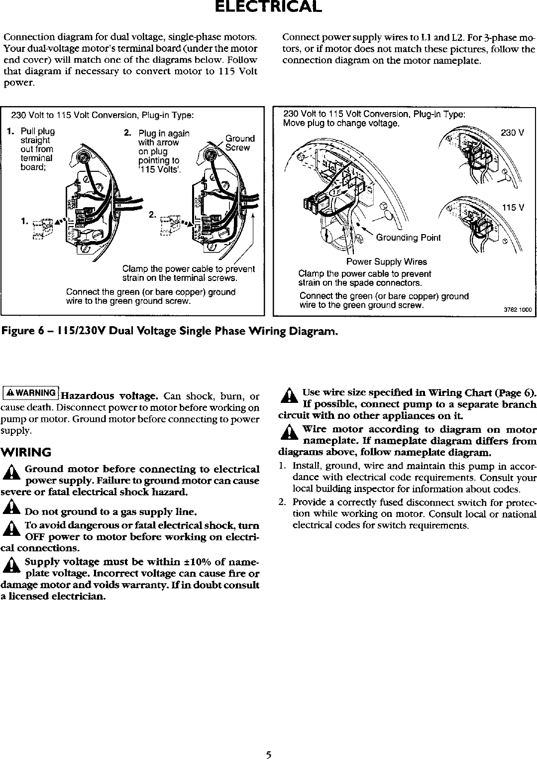


Craftsman User Manual High Pressure Sprinkler Pump Manuals And Guides L


Wire Size For Motor


Item Number Vr 40 165 Vr Series Switches For 115 Or 115 230 Voltage Vac Dual Voltage Capacitor Start Capacitor Run Motor On Torq Corporation


Doerr Electric Motors Wiring Diagram Electrical Engineering Progression Plan Nau Bege Wiring Diagram


Changing Voltage Speeds Of Single Phase Motors


Doerr Lr Motor Wiring Doityourself Com Community Forums


Electricity 101 Basic Fundamentals Industrial Controls


General Electric Motor Wiring Fine Homebuilding


Century Motor Wiring Diagram Wiring Diagram


Changing Old Air Compressor From 110 To 2v Adventure Rider
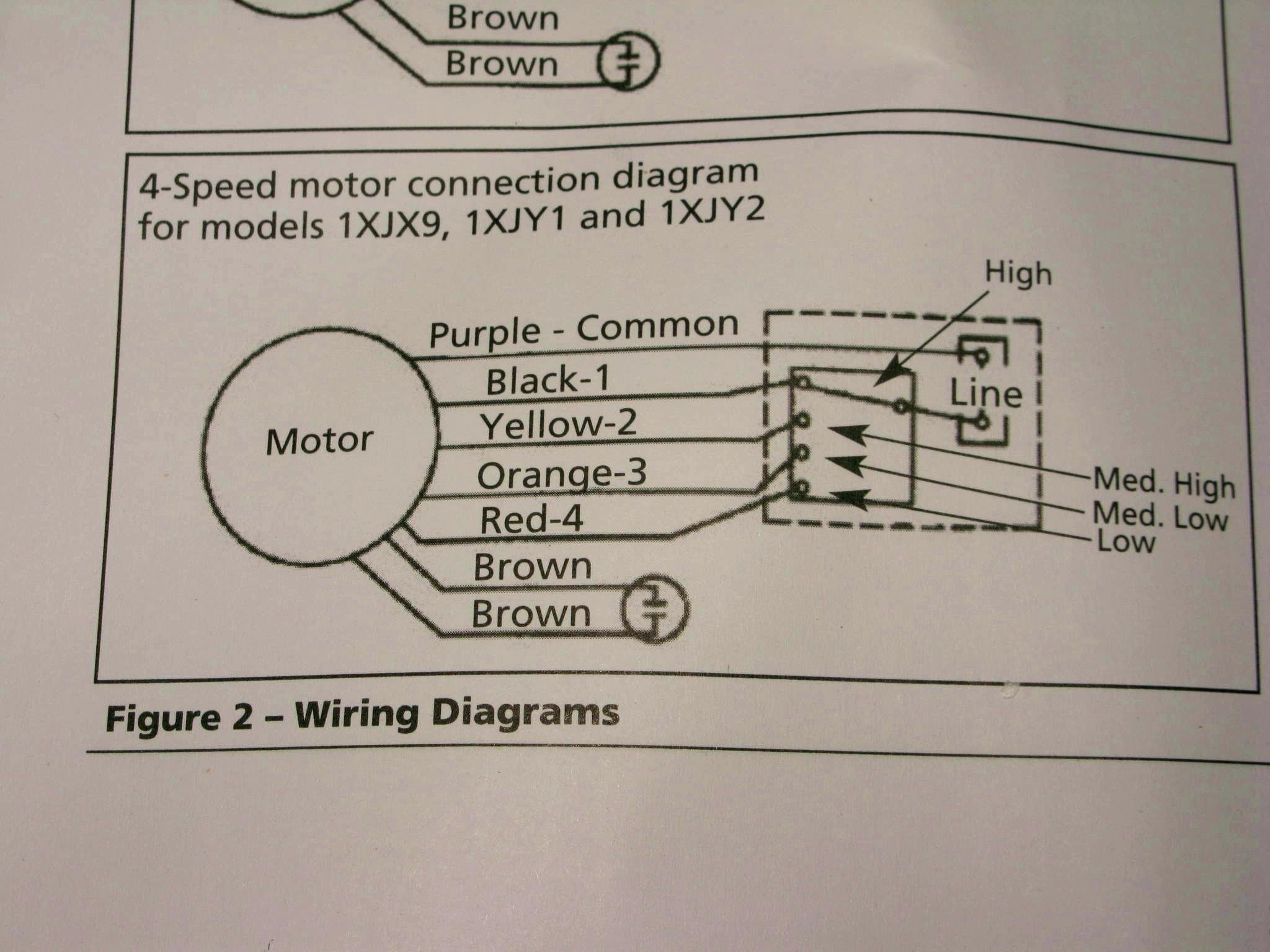


2 Hp Century Motor Wiring Diagram Celica Fuse Box Bege Wiring Diagram


Electricity 101 Basic Fundamentals Industrial Controls


480 Volt Motor Wiring Drone Fest
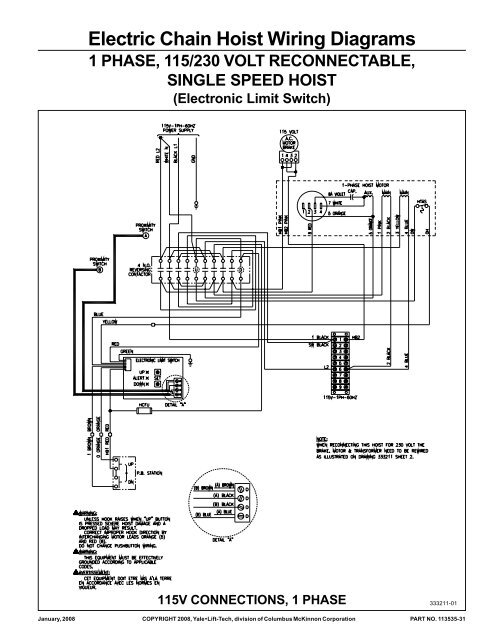


Electric Chain Hoist Wiring Diagrams Products On American Crane


Century Blower Motor Wiring Diagram Reverse Rotation 0 Mazda B2500 Fuse Box Diagram Bege Wiring Diagram


Dual Voltage Motors How They Work And Wiring Them Without The Wire Labels 059 Youtube


Www Egr Msu Edu Bae Sites Default Files Content Docs Technote103 Pdf


Century Electric Motors Wiring Diagram 115 Volt 316p760 Emerson Compressor Motor Wiring Diagram Schematic And Wiring Diagram


Diagram Century Ac Motor Wiring Diagram 115 230 Volts Full Version Hd Quality 230 Volts 6387 Vincentescrive Fr


Wiring Diagrams Manualzz
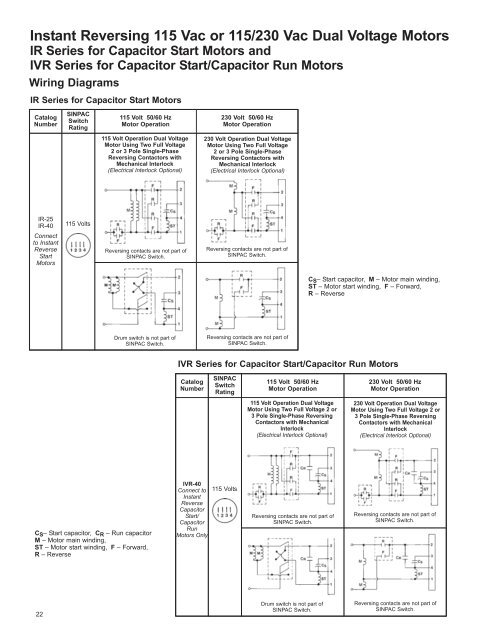


Instant Reversing 115 Vac Or 115 230 Vac Dual Stearns Rexnord


2 Speed Motor Wiring Need A Motor Guru Pre 1950 Antique Antique Fan Collectors Association Afca Forums


Waterway Pump Motor Century Motor 115v 12a One Speed 48fr Bn25 Bn25 7j06 0 1774 24 Lr4642 E 1 Bn25 S55cxgyn 8423


Capacitator With 115 Motor Wiring Diagram Wiring Diagram 00 Buick Regal Begeboy Wiring Diagram Source


Diagram 480 Vac Three Phase Wiring Diagram Full Version Hd Quality Wiring Diagram Mediagrame Ritabernardini It


Can You Explain How To Wire A Gould Century Motor To A Three Wire Cord What Wires Go To What Connection Are There
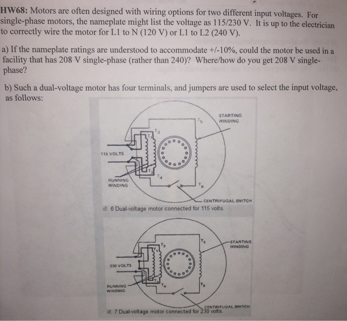


Solved Hw68 Motors Are Often Designed With Wiring Option Chegg Com


Q Tbn And9gcqdo4a1nsvaevwryueuscx3waoiaea45nt8dcticuv0ey5wlrcg Usqp Cau


Baldor Wiring Diagram 115 230 5 Wire Humbucker Wiring Diagrams Scotts S19 Au Delice Limousin Fr


Wiring Leeson From 230 To 115 Volts Youtube Youtube


Air Compressor To 110v Devilbiss Pro Air Doityourself Com Community Forums


Magnetek Century Motor Wiring Diagram Mopar 440 Engine Diagram For Wiring Diagram Schematics


Diagram Dual Voltage Single Phase Motor Wiring Diagram Full Version Hd Quality Wiring Diagram Speakerdiagrams Trattoriadeibracconieri It


Diagram Suzuki 230 Wiring Diagram Full Version Hd Quality Wiring Diagram Ladderdiagram Tickit It
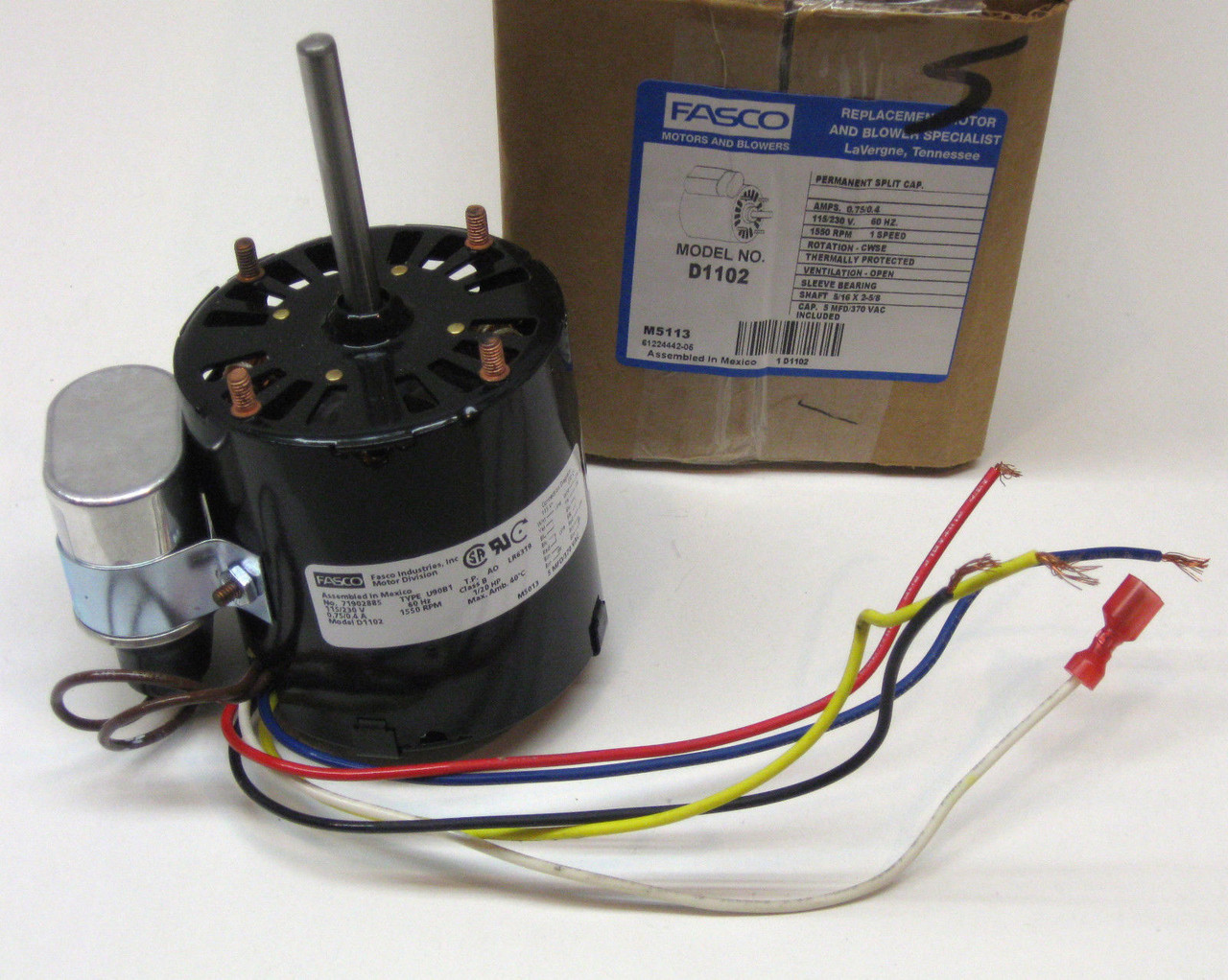


Fasco D1102 3 3 In Refrigeration Fan Motor 115 230 Volts 1550 Rpm Replacement For Witt Mccombs Supply Co Inc


Practical Machinist Largest Manufacturing Technology Forum On The Web


I Have A Chinese Made Single Phase Dual Voltage 115 230 Two Speed 700 14 Rpm Motor With No Motor Connection


Capacitator With 115 Motor Wiring Diagram Inverter Wiring Diagram Furnaces Tukune Jeanjaures37 Fr


Diagram 480v Motor Wiring Diagram Full Version Hd Quality Wiring Diagram Diagramofbrain Sciclubladinia It


2 Hp 115 230 3450 Rpm Marathon Air Compressor Motor Em03 0 36 10sp Ac Motors Base Mount Ac Single Phase Motors Electrical Www Surpluscenter Com


Diagram Hotpoint Motor Wiring Diagram Full Version Hd Quality Wiring Diagram Asmadiagram Spanobar It


3 4 Hp 115 230 Volt Ac 1140 Rpm Motor Dayton K56aaa01 Ac Motors Base Mount Ac Single Phase Motors Electrical Www Surpluscenter Com


Century Motor Wiring Diagram In Electrical Diagram Electrical Circuit Diagram Diagram


Ac Motor Speed Picture Century Ac Motor Wiring


Single Phase Induction Motors


Solved Hi I Have A Ao Smith S C56a05a19 Hp 3 4 Type C V 115 230 Fixya


Single Phase Electric Motor Wiring Tutorial Baldor Weg Leeson Youtube


Electric Motor Starting Capacitor Selection


2 Speed Motor Wiring Need A Motor Guru Pre 1950 Antique Antique Fan Collectors Association Afca Forums


Century Electric Motors Wiring Diagram Questions Answers With Pictures Fixya


Xm 7406 Dual Voltage Single Phase Motor Wiring Diagrams Wiring Diagram


Http Www Jbind Com Pdf Inst Motorconv Pdf


Wiring Motors High Or Low Voltage Electrician Talk


230 Volt Electric Motor Wiring Diagram 1977 Mustang Fuse Box Furnaces Tukune Jeanjaures37 Fr


Electricity 101 Basic Fundamentals Industrial Controls


Need Help With Marathon Electric Ac Motor Wiring


115 Volt Compressor Wiring Diagram Bremas Switch Wiring Diagram Rotary Rc85wirings Yenpancane Jeanjaures37 Fr


Swimming Pool Wholesale Warehouse At Pool1 Com Swimming Pool Pump Replacement Magnetek Centurion Motors


Diagram 9 Electric Motor Wire Diagram Full Version Hd Quality Wire Diagram Heatpumpdiagram Trattoriadeibracconieri It


Practical Machinist Largest Manufacturing Technology Forum On The Web


Www Egr Msu Edu Bae Sites Default Files Content Docs Technote103 Pdf


2 Speed Motor Wiring Need A Motor Guru Pre 1950 Antique Antique Fan Collectors Association Afca Forums


Ac Motor Sd Picture Wiring Diagram Century 72 Chevy Starter Wiring Diagram Hecho Begeboy Wiring Diagram Source


Baldor Wiring Diagram 115 230 07 F750 Wiring Harness Diagram Source Auto3 Yenpancane Jeanjaures37 Fr


Diagram 480v Motor Wiring Diagram Full Version Hd Quality Wiring Diagram Diagramofbrain Sciclubladinia It


コメント
コメントを投稿